A guided carriage moving in one direction can replace unnecessary robot joints in a fixed transfer, loading or indexing task, but only when the part path, grip and approach remain controlled. By the end, you will be able to determine whether one axis meets the motion, accuracy, speed, safety and maintenance demands of your cell, and identify when a different architecture is the better choice.
Key takeaways
- Use one guided axis when the part path is straight and access is simple.
- Match belt, screw, rack or linear-motor drive to speed, force and travel.
- Size payload, stroke, cycle time and positioning accuracy together.
- Validate the gripper, guarding, sensors and maintenance access before commissioning.
When one guided axis is the right robot for the task
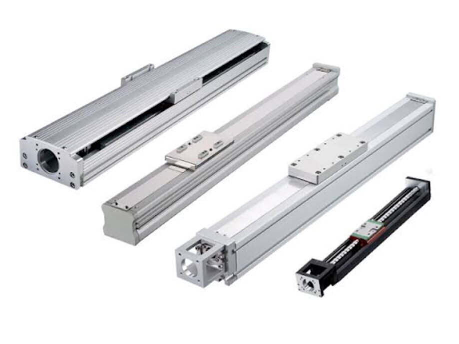
The single-axis robot definition is simple: a guided carriage moves an end effector along one linear axis, carrying a part between repeatable points. The carriage may use a belt, screw, rack or linear motor, while the gripper handles the part.
This arrangement improves a transfer operation when the path is straight, the approach direction stays fixed and the part does not need reorientation. It removes unused joints, reduces programming and homing tasks, and concentrates wear items in one guide, drive and cable route.
Useful pick-and-place examples include:
- Tray transfer between an input station and a downstream machine
- Press loading and unloading along a fixed front-to-back path
- Camera indexing that presents parts under a fixed inspection position
- Fixed-coordinate placement of components into nests or fixtures
A single axis also suits a station where a separate rotary mechanism handles orientation. That division can be easier to validate than a six-axis robot, but a product change that alters grasp location or obstacle clearance may require mechanical redesign.
Do not choose one axis if the tool must approach from changing angles, reach around obstructions, or correct large presentation errors. A multi-axis robot, Cartesian system or gantry fits those paths better.
Also check the failure consequence: one axis simplifies maintenance but becomes the transfer’s single point of failure, so high-throughput cells may need a bypass, spare carriage or replacement axis.
How the axis, gripper and machine complete one reliable cycle
A reliable cycle starts with the machine proving that the destination is ready and the part presentation is valid. Do not move into a missing tray, open fixture or occupied transfer zone; an interlocked PLC sequence prevents the axis from turning a sensing error into a collision.
1. Confirm part presentation with a presence sensor, correct orientation check or vision result. Keep the axis at a safe standby position until the PLC receives both “part ready” and “machine ready” signals.
2. Move to the pickup coordinate at controlled speed, then stop within the gripper’s permitted approach window. Close the gripper and verify grip using pressure, stroke, vacuum or part-presence feedback; a close command alone does not prove that the part is held.
3. Start acceleration only after the grip signal is valid. Use a motion profile that includes acceleration, constant-velocity travel and deceleration, rather than comparing the cycle with the axis’s advertised maximum speed.
4. Reach the placement coordinate, decelerate before the target and allow settling time. Higher acceleration can shorten a short stroke, but it also increases motor torque, guide loads and the chance of dropping or shifting the part.
5. Confirm the downstream fixture is ready, release the part and verify successful placement with a sensor or clamp signal. Then retract to a clear position before the machine begins its next operation.
6. Return the axis only after the PLC records placement complete. Validate the complete cycle with the actual gripper and payload, measuring tool-center-point results in both travel directions; axis repeatability alone does not prove placement accuracy.
How to size motion, payload and positioning performance
Calculate the complete profile, not the catalogue maximum speed. Your travel length and cycle time estimate must include loading time, gripper response, acceleration distance, constant-speed travel, deceleration distance, dwell time at pick and place, and return travel.
Test the target speed, acceleration and jerk against the payload and stroke; a short move may never reach target speed.
Check these inputs before accepting one-axis sizing:
- Payload mass and centre-of-mass offset from the carriage
- Pitch, yaw and roll moments, allowable radial loads, bearing life and guide load-position diagrams
- Duty cycle, peak force and RMS force over repeated reversals
- Positioning accuracy, bidirectional repeatability, resolution, backlash or reversal error, and settling time
- Actual tool-centre-point error with the gripper and payload, measured from both travel directions
| Specification | What proves suitability | What a miss causes |
|---|---|---|
| Stepper motor | Sufficient force margin for acceleration and friction at the required duty cycle | Lost steps and unknown position |
| Servo motor | Peak force, continuous force and thermal capacity, with encoder feedback | Overheating or force shortfall |
| Vertical axis | Holding capacity plus a vertical axis brake and safe torque off circuit | Dropped payload during power loss or shutdown |
Separate accuracy from repeatability: repeatability can be excellent while pitch, lead, encoder-scale or thermal error shifts the true coordinate. OLE Automation Inc can help match guide load data to the offset and moments; request the manufacturer’s calculations rather than relying on rated payload alone. Measure settling time at the intended speed before releasing the design.
Related products
 | MACHANICAL ₹2968 HGH-35-CA-ZOC / ZAC is a HIWIN size 35 linear guide block with heavy load capacity, designed for CNC and industrial automation. View product → |
 | MACHANICAL ₹1826 HGW-20-CC-ZOC / ZAC is a HIWIN size 20 flange-type (W series) linear guide block designed for CNC and industrial automation applications. View product → |
How to choose the drive, guides and catalogue configuration
Choose the architecture from travel length, speed, thrust, precision, maintenance, noise, and contamination tolerance—not payload alone.
| Option | Strength | Trade-off |
|---|---|---|
| ball-screw axis | High thrust, stiffness, precision | Screw critical speed and lubrication demand |
| belt-driven axis | Long travel, high speed, low mass | Belt elasticity, pretension, settling error |
| rack-and-pinion axis | Very long travel, continuous drive | Backlash, noise, lubrication, lower precision |
| pneumatic slide | Simple short stroke, low cost | Limited positioning and force control |
Use this pneumatic slide comparison table or worked examples before selecting a motor. A ball-screw axis suits pressing and vertical lifting; a belt-driven axis suits fast transfers; a rack-and-pinion axis suits long travel where precision allows backlash.
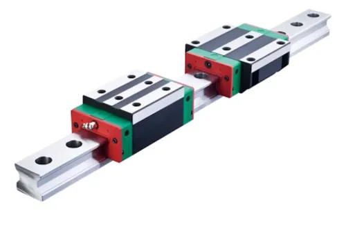
For the guide, increase rail spacing and block count when the tool has overhang, acceleration, or moment load. Compare preload: ZOC light preload reduces friction, while ZAC medium preload increases stiffness. A HIWIN guide block configuration comparison may include HGL-15-CA-ZOC/ZAC, HGW-20-CC-ZOC/ZAC, HGH-30-HA-ZOC/ZAC, HGW-25-CC-ZOC/ZAC, HGH-35-CA-ZOC/ZAC, and HGW-35-CC-ZOC/ZAC.
Check load ratings, static safety factor, moment ratings, and service life against the actual centre of gravity.
Specify rail parallelism, mounting-surface flatness, reference edges, and the bolt tightening sequence; poor alignment causes vibration and premature wear. Select lubrication for chips, dust, and washdown fluid, then add bellows, covers, or wipers where contamination enters. Catalogue limitations still apply: confirm deflection, mounting stiffness, thermal growth, and settling performance with the complete carriage and payload.
How to validate, safeguard and maintain the completed axis
Accept the axis only after mechanical, motion, safety and recovery tests use the actual gripper, fixture and payload. Catalogue repeatability cannot reveal settling time, compliance, vibration or a loose sensor.
1. Check guarding, access doors, emergency stops, pinch-point protection, safe torque off, hard limits, soft limits and braking. For a vertical axis, verify the brake holds static load and stopping energy; friction is not a restraint.
2. Validate homing sensors and homing accuracy after power cycles. Record the reference position, test sensor validation, and confirm a failed sensor creates a controlled fault rather than an unexpected move.
3. Run unloaded and loaded moves at production speed. Complete repeatability checks in both travel directions with the actual tool center point, including errors after acceleration and stopping.
4. Perform controlled collision testing at reduced speed, then verify fault recovery. Confirm the axis stops, removes drive torque, records the fault and requires a deliberate reset before restarting.
5. Perform alignment checks on guides, fasteners and the carriage. Schedule guide replacement from measured play; complete belt inspection for fraying and tension, or screw inspection for damage, contamination and lubrication.
6. Treat the axis as a single point of failure. Keep spare sensors and compare downtime against a quick-change carriage, bypass capability or spare axis before high-throughput production.
7. Document limits, brake tests, homing results, repeatability data and recovery steps. Rising vibration or settling time signals service before rejects or a crash.
Never bypass guarding or safety circuits to recover output. If bypass capability is needed for maintenance, use a keyed, logged mode with restricted speed and controlled access.
Frequently asked questions
When is a single-axis robot suitable for an operation?
Choose one when a guided carriage can move the end effector along one straight axis between repeatable points. Use a multi-axis robot when the task requires rotation, curved paths or coordinated movement in several directions.
How does a single-axis robot complete a reliable cycle?
The controller commands the axis to a programmed position, confirms arrival through feedback or sensors, actuates the gripper, and verifies part presence before returning or transferring the load.
What should you calculate when sizing a single-axis robot?
Calculate total payload, stroke, travel speed, acceleration, cycle time, external forces and required positioning performance. Include the gripper, tooling, cables and the part in the moving mass.
How do you choose the drive and guide configuration?
Compare belt, screw, rack and linear-motor drives against travel length, speed, force, accuracy and maintenance needs. Select guides that handle the payload, moment loads and mounting orientation.
How do you validate and maintain a single-axis robot?
Test the full loaded cycle, position repeatability, part detection, emergency stops and guarding before production. Follow the supplier's lubrication, inspection and belt, screw or guide adjustment intervals.
Related products
 | MACHANICAL ₹3228 HGH-30-HA-ZOC / ZAC is a high-precision linear guide block from the HIWIN HG series (size 30), designed for super heavy-load applications such as CNC... View product → |
 | MACHANICAL ₹3366 HGW-35-CC-ZOC / ZAC is a HIWIN size 35 flange-type (W series) linear guide block designed for heavy-duty CNC and industrial automation applications. View product → |
 | MACHANICAL ₹2262 HGW-25-CC-ZOC / ZAC is a HIWIN size 25 flange-type (W series) linear guide block designed for CNC and industrial automation. View product → |
 | MACHANICAL ₹1380 HGL-15-CA-ZOC / ZAC is a HIWIN size 15 low-profile linear guide block designed for compact CNC and automation applications. View product → |