A linear guideway does more than let a carriage travel along a rail: its rolling elements, preload, geometry and mounting determine how much friction, deflection and error reach the machine axis. By the end, you will be able to separate smooth motion from accuracy, size a guideway from real loads, and identify the installation and maintenance choices that protect performance.
Key takeaways
- Rolling elements reduce friction between the rail and moving guide block.
- Check load, pitch-roll-yaw moments and target service life before sizing.
- Select preload and accuracy grade to match stiffness and motion requirements.
- Protect raceways, lubricate correctly and verify runout during commissioning.
How the Rail and Guide Block Turn Sliding Into Rolling Motion
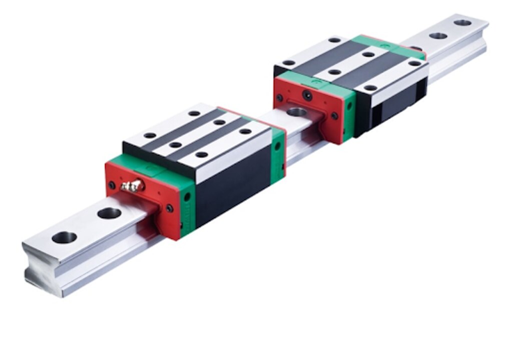
A linear guide rail provides the fixed track while the guide block carries the moving load. Inside the block, hardened raceways face matching raceways on the rail, creating rolling contact instead of direct sliding contact.
The ball rows carry the load and resist sideways movement, so the block follows a straight path rather than drifting or rotating.
As the block travels, each ball moves through its loaded raceway, exits into a return channel, and re-enters the load zone. This continuous circulation keeps the recirculating ball rows working through the full stroke.
Grease or oil reaches the contact zones through ports and internal passages, while end seals and wipers limit lubricant loss and chip entry.
Under clean, correctly lubricated conditions, rolling friction can be roughly 0.002–0.003. That low resistance reduces stick-slip and drive-force demand, but it is not friction-free: seal drag or excessive preload raises force, while contamination roughens motion and damages the raceways.
The guideway constrains travel, but a twisted mounting surface can still force the guide block into uneven contact.
Which Errors a Guideway Controls—and Which It Cannot
A guideway can make a carriage travel smoothly and hold its orientation, but it cannot make the machine accurate in every sense. Its raceways and preload constrain yaw, pitch and roll, while rolling contact provides stick-slip reduction; the drive, structure and installation still determine where the carriage actually stops.
| Measure | What the guideway improves | What can still cause error |
|---|---|---|
| Smoothness | Low rolling resistance and reduced stick-slip during travel | Contamination, poor lubrication, rail misalignment or excessive preload |
| Straightness | Constrains the carriage to the rail’s geometric path | Rail bending, mounting-surface flatness, rail parallelism and error over the measured length |
| Positioning accuracy | Limits deflection as the carriage moves under load | Ballscrew pitch error, encoder resolution, servo following error and thermal growth |
| Repeatability | Restores the carriage consistently after load changes when clearance is controlled | Backlash elsewhere, changing friction, thermal drift and control-system variation |
Preload improves stiffness and repeatability by removing internal clearance, but it does not correct a twisted bed or a bent rail. It can increase friction, heat and binding when mounting surfaces are inaccurate.
Thermal expansion changes rail spacing, preload and absolute position. Also, pitch, yaw and roll moments can load one carriage more heavily than another, so equal carriage count does not guarantee equal load sharing. A guideway constrains motion; calibration, compensation and the complete drive structure establish final machine accuracy.
How to Size a Guideway From Load, Moments and Service Life
Choose the rail and block from the calculated carriage load, not the machine’s overall size. Include payload, tooling, cable chains and fixtures, then add acceleration force using F = ma. Span between rails and block spacing determine pitch, yaw and roll moments, which can load one carriage far more than another.
Use this sizing sequence:
- Resolve vertical, lateral and acceleration forces into each carriage load; do not divide total weight evenly.
- Combine loads across the duty cycle into an equivalent dynamic load P, then apply the L10 life equation: L10 = (C/P)^3 × 50 km. Select a dynamic load rating C that delivers the required travel life.
- Check emergency-stop and impact loads separately with a static safety factor. A long fatigue life does not prevent raceway damage from a shock load.
- Compare calculated pitch, yaw and roll moments with the manufacturer’s moment capacity. Increase block size, block count or rail spacing when one moment exceeds the rating.
| Design check | What to calculate | Selection consequence |
|---|---|---|
| Dynamic life | Equivalent load P, duty cycle and required travel | Choose dynamic load rating C for the target L10 life |
| Static strength | Peak load during stops, impacts and faults | Meet the specified static safety factor |
| Moment resistance | Pitch, yaw and roll from load offset and span | Use larger blocks, wider spacing or additional carriages |
A larger block is not automatically better: it adds cost, mass and drive effort. Size the smallest arrangement that passes all three checks with documented manufacturer ratings.
How Preload and Accuracy Grade Change Motion Quality
Choose preload from the axis’s load changes and mounting quality, not from the highest stiffness rating. Preload removes internal clearance and limits elastic deflection, but excessive preload raises drive torque, operating temperature and binding risk. It also exposes rail misalignment that a clearance guide might tolerate.
| Preload | Motion effect | Suitable axis |
|---|---|---|
| light preload | Lowest friction, heat and noise; lower resistance to deflection | Long, fast axes with modest load changes |
| medium preload | Balanced stiffness and running resistance | General machining and automation axes |
| heavy preload | Highest rigidity and repeatability; greatest torque, heat and binding risk | Short, heavily loaded axes with rigid, accurately machined mounts |
Compare the accuracy grade by numbers, not labels. Manufacturers’ normal, high, precision and ultra-precision classes are not interchangeable: match running parallelism and height variation using the same reference length, measurement conditions and datum convention. A stated value over 100 mm is not a guarantee across a 2 m rail.
Check rail straightness, rail-to-rail parallelism and mounting-surface flatness separately. Thermal gradients can change preload and parallelism, while constrained rails can bend the axis. Use stable mounting, temperature control and compensation when absolute accuracy is tight; otherwise a precise rail can still produce rough, noisy motion.
How Installation, Lubrication and Protection Preserve Accuracy
Machine-bed accuracy starts with the reference surfaces, not the rail. Machine the mounting shoulders and seating faces in one setup, remove burrs and contamination, and verify flatness before placing the rail. Use the manufacturer’s tightening torque and a bolt tightening sequence that seats the rail progressively against its shoulder; random tightening can bow it.
- Set rail parallelism with a dial indicator or laser over the complete travel, not just at the ends. Align the second rail to the first while moving a fitted block, then tighten it incrementally.
- Apply the specified grease or oil through the guide block’s lubrication port, and relubricate according to travel, load and contamination. Too little lubricant scars the raceway; excess lubricant raises drag and heat.
- Protect the raceway with a cover or bellows and provide chip evacuation. Wipers and seals reduce ingress but cannot stop abrasive dust or chips that remain on an exposed rail.
- Move the block through a stroke long enough to redistribute lubricant. Repeating a tiny stroke leaves raceway sections dry and can cause false brinelling.
Temperature gradients change rail parallelism, preload and absolute position. Let the bed reach operating temperature, follow the machine designer’s fixed and expansion-mounting arrangement, and measure thermal compensation on long axes.
For HIWIN HGR rails, OLE Automation Inc can help match mounting practice and lubrication guidance to the selected size and accuracy class.
Related products
 | MACHANICAL ₹3186 HGR-20R C Class is a HIWIN size 20 linear guide rail designed for CNC and industrial automation applications. View product → |
 | MACHANICAL ₹3839 HGR-25R C Class is a HIWIN size 25 linear guide rail designed for CNC and industrial automation applications. View product → |
How to Verify Guideway Performance During Commissioning
Confirm performance by testing the installed axis under its real travel, load, speed and temperature—not by accepting the catalogue accuracy grade.
1. Home the axis, then run several cycles at the actual stroke length and operating speed. Record noise, vibration, motor current and any force peak at rail joints.
2. Use indicator measurement to check carriage straightness and parallelism at multiple positions, including both ends and every rail joint. Compare readings with the specified variation over the manufacturer’s stated measuring length.
3. Apply laser alignment when the axis is long or the tolerance is tight; it reveals rail-line error that a short indicator sweep can miss.
4. Run commanded moves in both directions and measure absolute position, repeatability and servo following error. Separate guideway error from screw pitch error, thermal growth and control error.
5. Complete a supplier data comparison using the same datum, reference length and temperature. Investigate failures after warm-up, then correct alignment or compensation before production.
A pass requires stable readings across the full stroke, not just an acceptable result at mid-travel. Recheck after the machine reaches operating temperature.
Frequently asked questions
How does a linear guideway turn sliding into rolling motion?
Hardened raceways on the rail and guide block contain rolling elements, such as balls or rollers, that carry the load while the block moves.
Which motion errors does a linear guideway control?
A guideway constrains carriage motion and resists pitch, yaw and roll according to its geometry, preload and load capacity. It does not correct a bent base, poor alignment or errors from the drive system.
How do you size a linear guideway?
Calculate the applied loads and pitch, yaw and roll moments, then compare the resulting equivalent load with the guideway’s dynamic load rating and required service life.
How do preload and accuracy grade affect motion quality?
Preload reduces clearance and increases stiffness, while accuracy grade limits rail and block dimensional variation. Higher preload and grade can increase friction, heat, cost and alignment sensitivity.
How do installation and lubrication preserve guideway accuracy?
Machine and clean the mounting surfaces, align the rails to the specified tolerance, use the recommended lubricant, and protect raceways from chips, coolant and dust.
Related products
 | MACHANICAL ₹3340 HGR-20R H Class is a HIWIN size 20 linear guide rail designed for CNC and industrial automation applications. View product → |
 | MACHANICAL ₹2685 HGR-15R C Class is a HIWIN size 15 linear guide rail designed for precision motion applications like CNC and automation systems. View product → |
 | MACHANICAL ₹5655 HGR-35R C Class is a HIWIN size 35 linear guide rail designed for CNC and industrial automation applications. View product → |
 | MACHANICAL ₹1826 HGW-20-CC-ZOC / ZAC is a HIWIN size 20 flange-type (W series) linear guide block designed for CNC and industrial automation applications. View product → |