A low-backlash gearbox can improve torque matching and output resolution, but it cannot by itself guarantee accurate motion. You will be able to calculate the error sources, select the correct ratio and interface, install the gearbox without adding new errors, and verify performance under the real load.
Key takeaways
- Separate gearbox backlash from encoder, structural and calibration errors.
- Choose the ratio using speed, torque, reflected inertia and duty cycle.
- Match gearbox input speed and torque capacity to the motor and load.
- Measure reversal error, repeatability and absolute accuracy after commissioning.
Define the Accuracy Problem Before Choosing the Gearbox
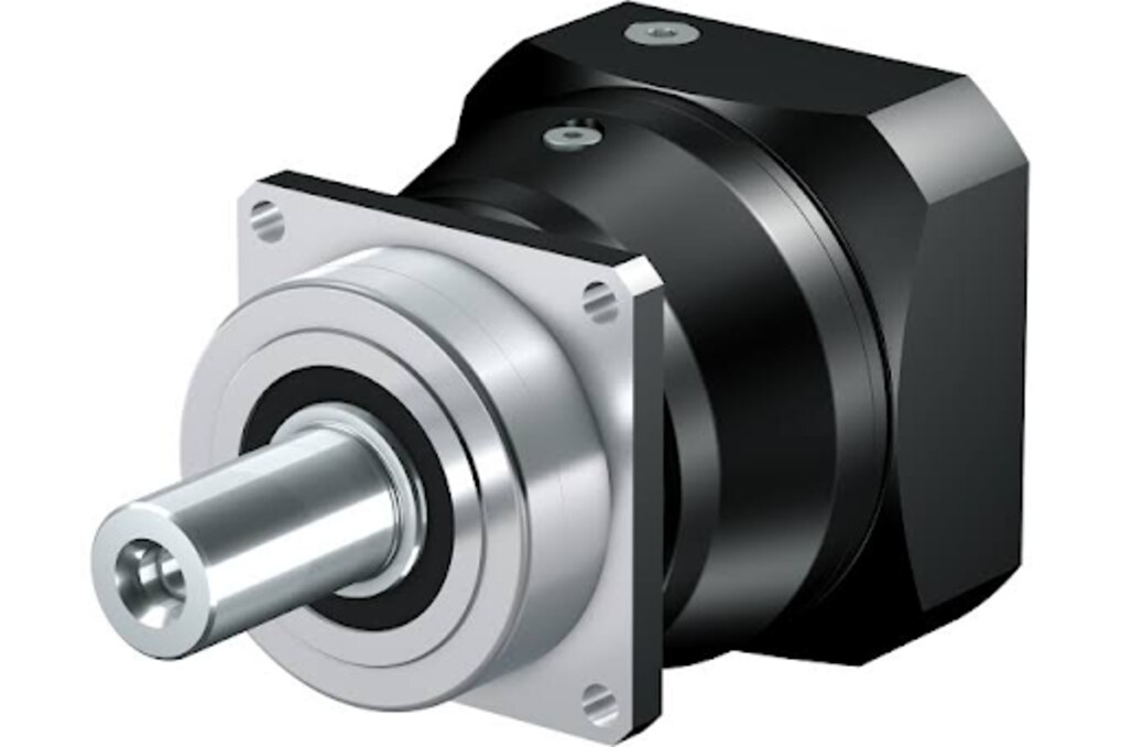
Stober gearbox accuracy can improve transmission-related errors, not every error in the axis. Output backlash is lost angular motion during reversal; it creates a position jump even when the motor encoder reports the commanded position. A low-backlash gearbox therefore improves reversal behavior, but it does not guarantee absolute positioning accuracy.
| Error source | What the gearbox can improve | What remains outside the gearbox |
|---|---|---|
| Output backlash | Reduces lost motion at direction changes | Residual backlash still appears at the output |
| Motor encoder resolution | A ratio can increase output-side angular resolution | Quantisation remains in the motor feedback signal |
| Shaft torsion and coupling compliance | A stiff gearbox can reduce transmission wind-up | Flexible shafts and couplings still deflect |
| External load deflection | Nothing, unless the gearbox is replaced with a suitably rated unit | Radial, axial and overturning loads bend the output shaft, bearings or structure |
| Linear-guide accuracy | Nothing | Rail alignment, preload, friction and linear-guide accuracy set tool motion |
Convert angular error at the actual point of interest. One arcminute produces about 2.9 µm at a 10 mm radius and 29 µm at 100 mm, so do not copy the gearbox figure directly into a linear-axis tolerance.
A motor-mounted encoder cannot see output-side wind-up while the load remains still. Use a load-side encoder when the application needs closed-loop correction after the gearbox, then check its cost and loop stability. Measure repeatability from both directions, reversal error, guide motion and thermal drift at operating temperature; one-direction testing can hide backlash.
Choose the Ratio from Speed, Torque and Inertia
Select the gearbox reduction ratio from the required output speed, not from torque alone. Output speed equals motor speed divided by the gearbox reduction ratio i. For a screw, motor speed must support the required travel rate through the screw lead; for a rack, travel rate depends on pinion speed, rack pitch and tooth count.
| Ratio choice | Control benefit | Main compromise |
|---|---|---|
| Low i | Preserves output speed and efficiency | Higher reflected load inertia and motor torque |
| Moderate i | Balances acceleration, resolution and cycle time | Requires stiffness and resonance checks |
| High i | Reduces reflected inertia to about Jload/i² and load torque to about Tload/i | Cuts output speed and can increase friction, compliance and reversal stick-slip |
Calculate continuous torque and peak acceleration torque separately. Include reflected inertia, gravity or process torque, friction, emergency-stop torque, duty cycle and the gearbox service factor; rated output torque alone is not enough. Check continuous thermal limits at the actual input speed, ambient temperature, mounting orientation and lubricant condition.
Use the actual ratio, payload inertia, coupling and torsional stiffness when tuning the servo. Raising gain to hide gearbox compliance can cause hunting, overshoot, gear noise or following-error trips. A frequency-response or stiffness check is safer than trial-and-error gain increases.
Leave margin for reversal: backlash, friction and torsional wind-up can dominate low-speed positioning even when the ratio improves encoder resolution. Choose the smallest ratio that meets acceleration and accuracy requirements without sacrificing the required travel rate.
Match the Gearbox to the Motor and Output Load
Do not approve a Stober gearbox from the reduction ratio alone. Match the exact gearbox series, model, ratio, input flange, and motor interface against the servo manufacturer’s dimensional drawing and the Stober selection data. A correct ratio with the wrong interface creates shaft misalignment, coupling preload, or an installation that cannot be serviced.
- Confirm the input flange, pilot diameter, shaft diameter, keyway and mounting-hole pattern match the motor or adapter plate. Check shaft engagement and coupling bore, not just nominal motor frame size.
- Compare the motor’s maximum speed with the gearbox input-speed limit, then check output speed at the selected ratio.
- Calculate continuous output torque and peak acceleration or reversing torque. Apply the specified service factor for duty cycle, shocks and frequent direction changes; do not size from peak torque alone.
- Calculate radial, axial and overturning loads at the actual pulley, tool or coupling distance. Compare each value with the gearbox output-shaft and bearing limits at operating speed.
- Check thermal capacity for ambient temperature, mounting orientation, lubricant and duty cycle. Continuous high-speed use can overheat a gearbox whose instantaneous torque remains within its mechanical rating.
Make the load path explicit. A large pulley, belt tension or offset tool can deflect the output shaft and bearings, while a flexible frame adds torsional error. OLE Automation Inc can help distinguish gearbox loads from linear-guide loads when checking whether the guide arrangement supports the external moment.
During assembly, control flange flatness, pilot seating, bolt tightening and coupling alignment; a low-backlash gearbox cannot correct those errors.
Install and Commission the Axis Without Adding Error
Control the assembly before tuning the servo: coupling misalignment, bearing runout, flange seating, housing stiffness and excessive coupling preload can add error that no gearbox specification removes. Verify the pilot diameter, flange flatness and shaft fits, then tighten mounting bolts in a controlled cross-pattern. The coupling must slide into position without forcing either shaft.
| Check | Failure caused | Control |
|---|---|---|
| Flange and pilot | Tilted gearbox and bearing load | Clean faces; measure seating and pilot fit |
| Coupling alignment | Radial or angular load, torsional error | Align shafts; check coupling runout |
| Lubrication and mounting orientation | Churning, heat, wear and changed lost motion | Use the specified lubricant quantity and orientation |
| Thermal condition | Drift, seal damage or shortened lubricant life | Check input speed, duty cycle, ambient temperature and housing heat transfer |
Commission the axis in this order:
- Record no-load temperature at the intended input speed, then repeat at the real duty cycle. Stop if temperature continues rising beyond the gearbox manufacturer’s limit.
- Tune the drive with the actual ratio, payload, coupling and torsional stiffness. Use a resonance or frequency-response check; raising gain to hide error can cause hunting, overshoot and following-error trips.
- Measure reversal error at the output, then separate backlash from encoder resolution, shaft torsion, guide deflection and structural growth.
- On a vertical or hazardous axis, validate a separate holding brake and safety function. Do not treat a gearbox’s resistance to back-driving as a safety-rated brake.
Prove the Accuracy and Decide Whether a Gearbox Is Right
Measure backlash at the output, not at the motor encoder. Lock the load, apply a small clockwise and counterclockwise torque, and record the output angle before motion begins. Convert the result at the point of interest: 1 arcmin produces about 0.029 mm at a 100 mm radius, but only 2.9 µm at 10 mm.
Run a bidirectional positioning test at operating temperature across the full travel. Compare commanded and measured positions after approaching from both directions, then repeat the move several times. Homing repeatability shows whether the reference routine is consistent; it does not prove absolute accuracy.
To isolate the error, check these signals and conditions:
- A large reversal error with stable motor feedback indicates backlash, coupling compliance, or torsional wind-up.
- Servo following error that rises during acceleration points to tuning, inertia, torque, or structural flexure rather than backlash alone.
- Error that changes with payload position or belt tension indicates bearing deflection, guide preload, rail alignment, or an offset load.
A load-side encoder measures the error the motor encoder cannot see, but it adds cost and loop-stability work. Do not cure mechanical error by raising gain; resonance can cause hunting, gear noise, overshoot, or following-error trips.
Choose the architecture that matches the measured failure:
| Option | Best fit | Main limitation |
|---|---|---|
| Gearbox | High torque, compact servo axis | Backlash and torsional compliance |
| Direct drive | Zero transmission backlash | Requires a larger motor and high continuous torque |
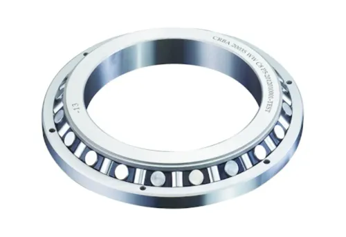
| Low-backlash or cross-roller architecture | Reversing, stiff positioning | Higher cost and tighter alignment demands |
Frequently asked questions
What accuracy problem can a Stober gearbox solve?
A low-backlash Stober gearbox can reduce lost angular motion during reversal, but it cannot correct encoder, structural, thermal or calibration errors elsewhere in the axis.
How do you choose the gearbox ratio?
Select the ratio from required output speed, motor speed, output torque, reflected load inertia and the machine’s duty cycle.
How should you match a gearbox to the motor and load?
Check motor input speed, continuous and peak torque, permitted radial and axial loads, inertia limits, mounting arrangement and output shaft dimensions.
How do you commission a gearbox without adding positioning error?
Align the gearbox and coupling, tighten fasteners to the specified torque, eliminate coupling preload, configure the drive correctly and tune the axis after mechanical installation.
How do you prove whether the gearbox improved accuracy?
Measure reversal error, bidirectional repeatability, unidirectional positioning accuracy and absolute position against a calibrated reference before and after installation.