A gearbox that matches the motor’s nameplate torque can still fail when acceleration, reflected inertia, overhung loads, thermal limits or positioning errors enter the calculation. By the end, you will have a practical method for sizing a Neugart gearbox, checking motor and load compatibility, and validating precision performance from the datasheet and your motion profile.
Key takeaways
- Calculate torque across acceleration, travel, deceleration, reversal and emergency stop.
- Choose frame size and ratio from output torque, speed, duty cycle and motor fit.
- Check reflected inertia, backlash, torsional stiffness and output-bearing loads together.
- Request the complete datasheet, sizing calculation and application limits before ordering.
How do you calculate the gearbox torque your motion profile actually requires?
1. Build the output torque calculation from the complete motion profile, not motor nameplate torque alone. Divide the cycle into acceleration, constant-speed travel, deceleration, dwell, reversal and emergency stop, then calculate the required output torque in each phase. A payload torque that looks harmless during travel can dominate acceleration or a hard stop.
2. For a rotary load, calculate acceleration torque with T = J × α, where J is total load inertia at the gearbox output and α is angular acceleration. Add friction torque, gravity torque, belt or leadscrew resistance, and any cutting or process force converted to output torque.
For a linear axis, convert force using the screw lead, pulley radius or rack-and-pinion pitch radius, then include transmission efficiency. For a screw, T = F × lead ÷ (2π × efficiency); for a pulley or rack, use T = F × radius ÷ efficiency.
3. Reflect the load inertia to the motor through the selected gearbox ratio and transmission arrangement. Check the highest instantaneous torque separately from root-mean-square torque over the duty cycle; a gearbox that survives one peak can still overheat under repeated reversals.
4. Apply a safety factor based on machine risk, shock loading and friction uncertainty. Do not conceal repeated overloads inside one oversized generic margin. Record acceleration time, cycle frequency, dwell time, reversal count and emergency-stop frequency because each affects peak torque and thermal loading.
How should you choose the Neugart gearbox series, frame size and ratio?
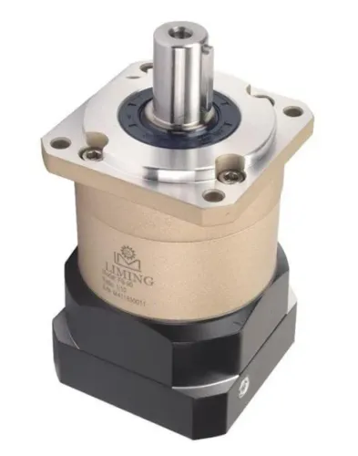
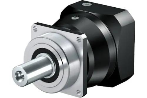
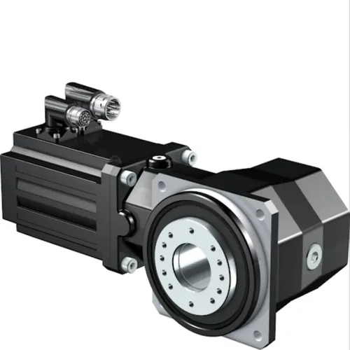
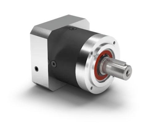
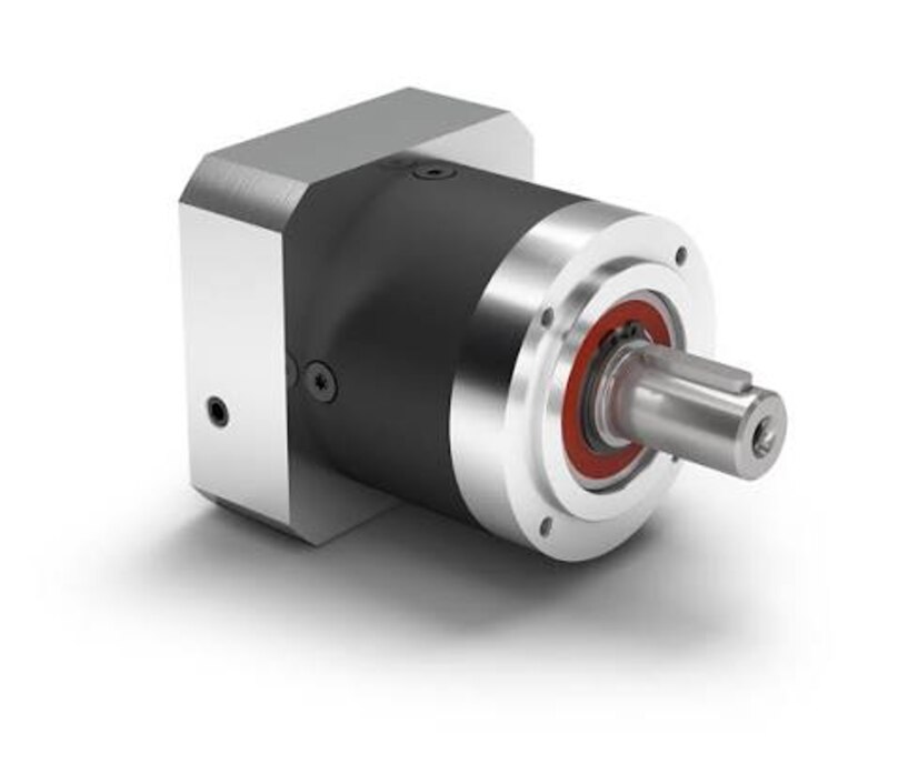
Match the gearbox layout to the axis before comparing frame sizes. A planetary gearbox suits a compact servo axis needing high torque density, low lost motion and coaxial motor-to-load packaging. A right-angle gearbox suits limited motor clearance, difficult cable routing or a tight machine envelope where a straight power path matters less.
| Layout | Main advantage | Check before choosing |
|---|---|---|
| Planetary | Coaxial packaging and high torque density | Lost motion, torsional stiffness, bearing capacity and thermal margin |
| Right-angle | Motor clearance and compact routing | Efficiency, output-load capacity, mounting space and permissible speed |
Use the current Neugart selection tables to compare each Neugart gearbox series by continuous torque, permissible peak torque, ratio range, output speed, efficiency, torsional stiffness, bearing capacity, backlash or lost motion, and mounting options. Do not compare planetary gearbox ratings by torque alone; stage count, allowable speed and package size can change the result.
Complete frame size selection only after checking the load case. A nominal output rating is not continuous torque at every speed: thermal capacity, ambient temperature, mounting orientation, duty cycle and ratio-specific efficiency can reduce it. Treat continuous, peak, emergency-stop and permissible output torque as separate limits.
Confirm peak-event frequency, and assess repeated hard stops as a fatigue or service-life issue.
Choose the ratio from required output speed and motor speed. Then verify that it preserves sufficient continuous and peak motor torque, output speed, backdrivability and servo bandwidth.
How do ratio, motor fit and reflected inertia affect servo performance?
Calculate the gearbox reduction ratio from the required output speed first: ratio = motor speed ÷ output speed. Then test how that ratio changes resolution, available torque and servo tuning.
A higher gearbox reduction ratio generally increases output torque and reduces load inertia reflected to the motor, approximately by the square of the ratio. It also lowers output speed, reduces backdrivability and adds mesh losses in multistage designs.
- Confirm that motor encoder resolution, gearbox ratio and mechanism pitch produce the required output positioning increment. An excessive ratio can make each servo command too sensitive to encoder counts, while an insufficient ratio can leave torque or resolution short.
- Reflect the mechanism inertia through the selected ratio, then compare the resulting load-to-motor inertia ratio with the motor and drive manufacturer’s recommendation. Do not assume the gearbox makes every inertia mismatch acceptable; poor matching can cause overshoot, hunting or slow settling.
- Check the Neugart adapter drawing for motor flange dimensions, pilot diameter, shaft diameter and keyway, usable shaft length, clamp connection, bolt pattern and any required spacer.
- Verify allowable motor-side radial and axial loads, motor rotor inertia and maximum input speed. A motor can be electrically suitable yet mechanically incompatible when its shaft length, pilot or adapter pattern is wrong.
- Request the exact motor-gearbox combination drawing, not only a nominal motor frame designation. That drawing exposes fit, clearance and coupling errors before assembly.
How do output loads and precision specifications determine whether the gearbox is suitable?
A gearbox is suitable only when its output torque and load capacity both pass the application’s limits. Check radial load, axial load and tilting moment separately from torque.
A pulley, sprocket, pinion, leadscrew or rotary table applies force at a distance from the gearbox mounting face. Use the Neugart load tables for force direction, overhung distance, output speed and bearing arrangement.
A separate bearing set can carry the pulley or table load, leaving the gearbox to transmit torque; if the gearbox supports that load directly, the required frame size can increase even when torque is modest.
| Specification | What it describes | What it does not prove |
|---|---|---|
| Backlash | Angular clearance under a stated test condition | Loaded bidirectional repeatability |
| Torsional rigidity | Resistance to elastic wind-up | Zero positioning error |
| Hysteresis | Difference between reversing directions under load | Absence of bearing or shaft compliance |
| Lost motion | Total output movement not immediately commanded | Interchangeability with an angular backlash value |
Do not compare figures unless the definition, test load and measurement method match. Backlash is distinct from elastic wind-up, bearing compliance, shaft deflection, coupling compliance and servo following error. Motor-side encoder feedback cannot measure every output-side error.
For high-acceleration axes, verify torsional stiffness and separation between torsional natural frequency and excitation frequencies. Resonance can extend settling time and damage contour accuracy.
Define acceptance tests before purchase: loaded bidirectional repeatability, settling time, output-shaft runout and total lost motion. Check coolant, abrasive dust, washdown, vacuum, temperature and mounting orientation at the gearbox interface, because these conditions affect sealing, lubricant behaviour and service life.
What should you verify in the final datasheet review and supplier discussion?
Freeze a selection record that links every gearbox choice to a measured requirement. Include:
1. Motor model, adapter drawing, ratio, input and output speed, continuous torque, peak torque, RMS torque, emergency-stop torque, cycle timing, load inertia, radial and axial forces, overhung distance, ambient conditions, mounting orientation and expected service life.
2. During the Neugart datasheet review, ask the supplier for the exact test conditions behind backlash, lost motion, efficiency, torsional stiffness and permissible output-load figures. Do not compare a catalog backlash value with lost motion unless load, speed and measurement method match.
3. Confirm lubricant, sealing or protection limits, gearbox service requirements, output-shaft runout, bearing-life assumptions and the procedure for replacing or inspecting the assembly. Record acceptance limits for loaded bidirectional repeatability, settling time and runout.
Use a loaded prototype test to expose errors from the coupling, mounting face, machine frame and separate bearings. OLE Automation Inc can help reconcile the Neugart drawing with the motor, coupling, leadscrew, pulley or rotary-table interface when the motion profile and load-path drawing are available, rather than only the motor part number.
That evidence supports a decision based on usable precision, thermal margin and serviceability—not the smallest catalog backlash or highest isolated torque figure.
Frequently asked questions
How do you calculate the gearbox torque your motion profile actually requires?
Divide the cycle into acceleration, constant-speed travel, deceleration, dwell, reversal and emergency stop, then calculate output torque for each phase. Select against the highest valid torque, including payload, friction, acceleration and stopping loads.
How should you choose the Neugart gearbox series, frame size and ratio?
Match the series to the required precision, duty cycle and application geometry. Choose a frame size that handles continuous and peak torque, then select a ratio that meets output speed without exceeding input speed or motor limits.
How do ratio, motor fit and reflected inertia affect servo performance?
The ratio changes output speed, torque and reflected load inertia. Confirm the motor mounting interface, shaft dimensions and allowable input speed, then check the reflected inertia ratio for servo settling and stability.
How do output loads and precision specifications determine whether the gearbox is suitable?
Compare radial, axial and moment loads with the gearbox limits, and verify backlash, torsional stiffness, repeatability and positioning accuracy against the machine requirement.
What should you verify in the final datasheet review and supplier discussion?
Confirm torque ratings, speed, ratio, efficiency, backlash, thermal limits, lubrication, mounting dimensions, motor compatibility, load limits and the sizing assumptions used for your motion profile.