A bearing lock nut must do more than match the shaft thread: it must seat the bearing squarely, establish the correct axial position, and stay locked under vibration and operating temperature. By the end, you will be able to compare locking methods, verify nut and bearing dimensions, and install the assembly without creating excessive preload or losing axial control.
Key takeaways
- Match the nut thread, diameter, and locking method to the shaft and bearing.
- Use fine threads when precise axial adjustment and higher holding force are needed.
- Set preload or end play with measured torque, not guesswork or impact tools.
- Recheck the lock nut after running the assembly through its operating temperature range.
How a Bearing Lock Nut Holds the Assembly in Position
A bearing lock nut presses the bearing’s inner ring against a positive shaft shoulder, sleeve face, or precision spacer. That clamp prevents axial movement and stops reversing or shock loads from driving the ring along the shaft.
The shoulder provides location; the nut supplies retaining force, so friction alone is not a reliable defence against bearing creep or preload loss.
On a cylindrical seat, the nut establishes bearing position and, in a matched angular-contact or tapered-roller pair, sets operating preload or endplay. Tightening until the assembly merely feels tight can create excessive preload, temperature rise, lubricant breakdown, smearing, or seizure.
On a tapered seat, follow the specified axial drive-up or radial internal-clearance reduction instead of relying on nut torque alone.
| Method | How it holds the assembly | Main difference |
|---|---|---|
| Bearing lock nut | Threads onto the shaft and clamps the inner ring | Precise axial setting; fine threads give small movement per turn |
| Lock washer | Locks the nut mechanically through a tab and shaft keyway | Prevents nut rotation but does not locate the bearing by itself |
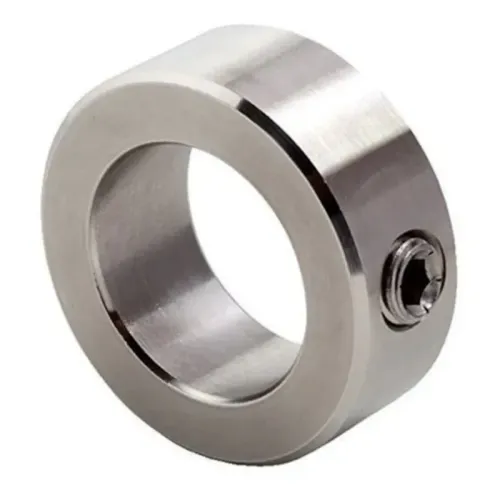
| Shaft collar | Clamps around the shaft surface | Quick retention, but relies on collar grip and available shaft area |
| Threaded end plate | Bolts to the shaft end or housing | Needs end-face access and adds parts |
| Clamping nut | Pinches a split or threaded component onto the shaft | Depends on clamping friction rather than a positive shoulder |
| Adhesive threadlocker | Bonds mating threads after curing | Resists loosening but complicates adjustment and removal |
Match the Nut to the Shaft, Bearing, and Housing
Match the lock nut to the complete assembly, not the nominal shaft diameter alone. Confirm the shaft’s thread form, pitch, handedness, and usable threaded length against the nut specification.
Then check the bearing designation, mounting arrangement, inner-ring abutment, and chamfer; these determine whether the nut face supports the ring without touching its transition radius or seal.
| Check | What must match | Failure if ignored |
|---|---|---|
| Thread | Shaft thread form, pitch, handedness, diameter, and engagement length | Cross-threading, insufficient holding force, or a nut that cannot reach the bearing |
| Nut series | KM-series nut with its specified MB-series washer and matching shaft keyway | The washer tab cannot engage the keyway or the nut slot |
| Nut dimensions | Face diameter, width, slots or wrench flats, and inner chamfer | Partial inner-ring contact, seal interference, or no room to tighten |
| Bearing interface | Abutment diameter, ring chamfer, and shoulder fillet | The ring tilts instead of seating squarely |
| Housing clearance | Nut outside diameter, width, and access for the tightening tool | The nut contacts the housing or cannot be adjusted |
Before ordering, compare the manufacturer’s dimensional drawing with the shaft and housing drawing. Verify that the shaft shoulder and nut face are square to the axis; burrs, dirt, or an oversized fillet can create runout and uneven raceway loading.
- Record the bearing designation and whether it sits on a cylindrical or tapered seat.
- Confirm the required nut series, washer thickness, keyway dimensions, and slot count.
- Check that the nut reaches full thread engagement while leaving clearance for the bearing seal and housing.
Choose Fine or Coarse Threads and the Right Locking Feature
Choose the locking system by adjustment, vibration, and service access—not by thread size alone. A fine thread gives smaller axial movement per turn, useful for setting bearing preload precisely, but contaminated or damaged threads cross-thread easily. Use a coarse thread for rugged handling, faster assembly, or dirty service where precision adjustment matters less.
| Option | Main advantage | Choose it when |
|---|---|---|
| Fine thread | Precise axial adjustment | You need accurate preload or end-play control. |
| Coarse thread | Faster, tougher assembly | The shaft sees dirt, impact, or frequent handling. |
| Tab washer | Visible positive mechanical retention | Vibration is high, the shaft has a keyway, and dismantling is infrequent. Replace the washer after removal. |
| Set screws | Keyway-free locking and fine angular adjustment | You can provide the specified screw torque and a suitable shaft surface. Follow the manufacturer’s tightening sequence. |
| Clamping design | Even grip without a keyway | You need strong retention on an undamaged shaft and want to avoid point loading from screws. |
| Adhesive threadlocker | Simple secondary resistance to loosening | The joint stays clean, oil-free, within the adhesive’s temperature range, and is rarely dismantled. |
Match the nut’s handedness to shaft rotation; a rotating assembly with the wrong thread direction can loosen under load. Treat a locking clip or tab washer as part of the designed system, not as a substitute for the specified nut, washer, or screw procedure.
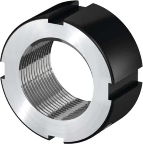
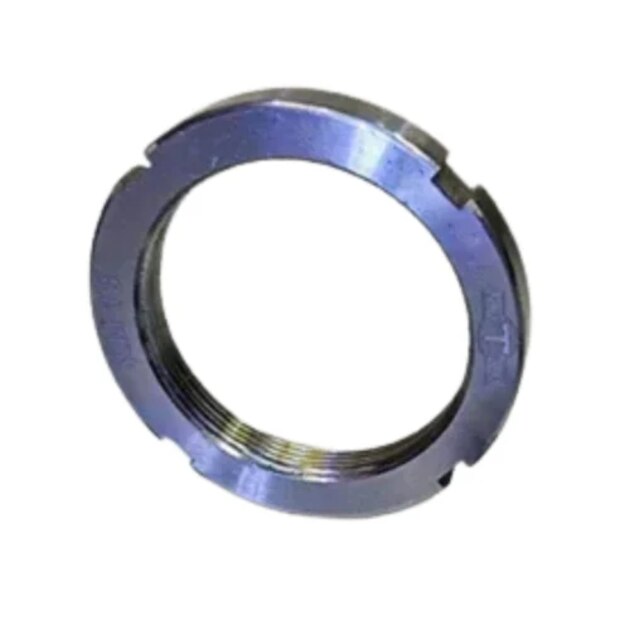
A KM nut with an MB washer needs its matching keyway and slot arrangement.
Set Preload or End Play Without Damaging the Bearing
Adjust the lock nut against the bearing maker’s specified setting, not until the shaft merely feels tight. On a cylindrical seat, the nut normally positions the bearing against its shoulder; set bearing preload or axial clearance through the prescribed spacer, shim, or nut torque rather than forcing the inner ring.
| Seat type | Adjustment method | Main warning |
|---|---|---|
| Cylindrical seat | Bring the nut up to the specified torque or axial position, then verify shaft rotation and end play | Excess force can distort the bearing or remove designed clearance |
| Tapered seat | Measure axial drive-up or reduction in radial internal clearance | Nut torque alone does not show the bearing’s actual position |
| Paired angular-contact or tapered-roller bearings | Follow the pair manufacturer’s sequence, rotating the assembly during adjustment when specified | Tightening until resistance feels high can create excessive preload |
For a tapered bore, a hydraulic nut applies mounting force while you control the specified displacement or clearance reduction. Use its pressure-to-position procedure; do not substitute a pressure guess or the nut’s maximum capacity.
Fine threads help make small axial adjustments, but clean the threads before turning the nut. Excessive tightening can cause rapid temperature rise, lubricant breakdown, smearing, or seizure. After setting the pair, release and reapply the nut only as the manufacturer directs, then confirm the final preload or end play with the specified measurement method.
Install, Secure, and Recheck the Shaft Assembly
A reliable installation starts with a clean, square shaft shoulder, not with tightening the nut. Remove burrs and dirt, confirm that the bearing chamfer clears the shoulder fillet, and inspect the thread engagement for damage. Use a matching washer and nut series; a nominal thread match alone does not confirm correct seating or slot alignment.
1. Press the bearing inner ring firmly against the shaft shoulder, applying force only through the inner ring. Rotate the shaft or bearing during adjustment when the bearing-pair manufacturer specifies it.
2. Fit the locking washer or other locking feature, then run the nut on by hand. Stop if it binds before full thread engagement; forcing it can cross-thread a fine-thread nut.
3. Tighten to the manufacturer’s validated setting while checking the specified preload or end play measurement. Treat nut torque as an assembly control, not a universal preload value, because lubrication and surface friction change the result.
4. Secure the nut: bend the washer tab into a slot, tighten the set screw against the shaft flat, or clamp the nut according to its design. Mark the nut and shaft so movement is visible.
5. Run the assembly at low speed, monitor temperature, noise, and vibration, then stop and let it cool. Recheck the mark, locking feature, nut torque where appropriate, and end play measurement. OLE Automation Inc can help verify that replacement motion components match the shaft drawing rather than relying on diameter alone.
Frequently asked questions
How does a bearing lock nut hold a shaft assembly in position?
It clamps the bearing’s inner ring against a shaft shoulder, sleeve face, or precision spacer, preventing axial movement under reversing or shock loads.
How do you match a bearing lock nut to the shaft, bearing, and housing?
Confirm the shaft thread diameter and pitch, bearing bore and inner-ring width, shoulder geometry, available wrench clearance, and housing alignment before selecting the nut.
Should you choose a fine or coarse thread for a bearing lock nut?
Choose a fine thread when you need precise axial adjustment, greater thread engagement, or more resistance to loosening; use a coarse thread when fast assembly and damage tolerance matter more.
How do you set bearing preload or end play without damaging the bearing?
Use the bearing maker’s specified torque, end-play, or preload method, rotate the shaft while seating the rollers, and avoid impact tools that can brinell the races.
How should you install and recheck a bearing lock nut?
Clean and inspect the threads, tighten the nut squarely, engage the locking feature fully, verify shaft rotation and measured end play, then recheck after the first operating cycle.