A gearbox choice based only on motor torque can fail when acceleration, repeated reversals, external loads, heat, or emergency stops enter the machine cycle. By the end, you will have a practical method for calculating the required ratings, choosing a ratio and arrangement, checking compatibility, and preparing a specification that a supplier can verify.
Key takeaways
- Start with output motion, load torque, inertia, and duty cycle.
- Select ratio from speed, cycle time, and reflected inertia.
- Compare backlash, torsional stiffness, efficiency, and servo response.
- Give suppliers output loads, motor details, mounting, and operating conditions.
Start with the complete motion profile, not the motor nameplate
Calculate the gearbox from the machine’s complete motion profile, not from motor nameplate power or motor torque alone. Define the required output speed, load torque, acceleration and deceleration torque, reflected inertia, duty-cycle duration, and thermal rest periods before comparing ratings.
1. Calculate the normal running case: output torque at each speed, acceleration torque, continuous torque, cycle time, and total operating time. Include the number of starts and reversals per hour; repeated cycling can create heat and fatigue even when average torque looks low.
2. Convert motor torque to gearbox output torque using the manufacturer’s efficiency data for the exact ratio and stage count. Do not assume 95 percent efficiency: speed, temperature, lubrication, and operating condition change the result.
3. Calculate peak torque during the fastest acceleration, deceleration, load changes, and direction reversals. Compare that value with the gearbox’s permissible peak torque, maximum torque, and service factor rather than checking only continuous torque.
4. Treat an emergency stop and a collision as separate load cases. Record event torque, stopping method, brake response, duration, and repetitions, then compare each with the stated emergency-stop limit. One allowable peak event does not validate repeated impacts.
For a vertical axis, calculate the static holding torque and stopping energy after power removal. Check backdriving, motor-brake capacity, and the need for a separate mechanical holding device; gearbox torque capacity is not a fail-safe brake.
This calculation is the foundation of Neugart gearbox selection. A gearbox that passes continuous torque can still fail through repeated peak torque, torsional fatigue, or inadequate thermal capacity.
Choose the ratio from output speed, cycle timing, and reflected inertia
Set the gear ratio from the required output speed, using i = motor speed ÷ output speed. If the axis needs 120 rpm and the motor operates at 2,400 rpm, 20:1 is the nominal starting point, not the final selection. Check the ratio against acceleration time, dwell time, reversal frequency, and the motor’s maximum speed.
A higher ratio reduces reflected load inertia approximately by i², so the servo sees a lighter load. It also reduces output speed, weakens backdrivability, and can worsen disturbance response or settling when gearbox compliance dominates the axis. A lower ratio preserves responsiveness but passes more load inertia back to the motor.
| Ratio choice | Effect on the axis | Servo-tuning consequence |
|---|---|---|
| Low reduction | Higher output speed and higher reflected inertia | Faster disturbance response, but greater acceleration torque and motor demand |
| Moderate reduction | Balanced speed, inertia, and torque multiplication | Usually the easiest range to tune across a varied cycle |
| High reduction | Lower output speed and much lower reflected inertia | Lower motor torque demand, but poorer backdrivability and potentially longer settling |
For each candidate, calculate acceleration torque, load torque, and peak and RMS motor torque across the complete cycle. Convert motor torque to output torque using the manufacturer’s efficiency for that exact ratio, stage count, speed, and temperature; do not assume 95 percent.
Reject a ratio that reaches the required output speed only by driving the motor at its limit, or that meets torque while exceeding the gearbox’s thermal duty rating during repeated starts and reversals.
Compare gearbox arrangements by servo-axis performance
Compare arrangements beyond torque and envelope as soon as the axis reverses, settles, runs at high speed, or faces a right-angle packaging constraint. A static torque match will not reveal lost motion, torsional resonance, thermal derating, or collision-load damage.
| Arrangement | Servo-axis strength | Trade-off to check |
|---|---|---|
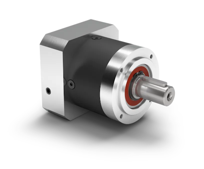
| Planetary gearbox | High torsional stiffness, coaxial packaging, and low backlash suit rapid reversals and precise positioning | Efficiency changes with ratio, stage count, speed, temperature, and duty; calculate output torque with the manufacturer’s exact data |
| Inline helical gearbox | Smooth, quiet transmission and efficient continuous running suit moderate-speed axes with straightforward coaxial mounting | Compare torsional stiffness, backlash, input speed, and output-bearing loads rather than assuming smooth operation guarantees fast settling |
| Helical-bevel gearbox | Right-angle output can shorten the machine and simplify a constrained axis layout | Check angular stiffness, backlash, bearing loads, noise, and mounting orientation; the housing arrangement can reduce thermal margin |
Check catalog backlash only at its stated load and measurement condition. It is not the same as total axis positioning error, which also includes coupling, shaft, bearing, and structure deflection. Low torsional stiffness can leave a resonance or slow settling tail after the servo reaches its commanded position.
Use the exact efficiency figure when converting motor torque to gearbox output torque. Review emergency-stop and collision events separately, including duration, brake response, repetition, and the gearbox’s permissible peak and emergency-stop limits. Then verify continuous torque at actual speed, ambient temperature, airflow, orientation, and duty cycle; thermal capacity can disqualify a mechanically adequate gearbox.
Check output loads, motor fit, mounting, and operating conditions
A gearbox can meet its torque rating and still fail in service if the pulley offset, motor adapter, heat, or environment exceeds its limits. Complete these checks against the exact gearbox configuration before ordering.
1. Calculate output bearing loads at the real mounting geometry. Combine radial load, axial load, and the overturning moment from any pulley, sprocket, or belt at its distance from the mounting face. Do not rely on the headline radial-load figure.
Check bearing life separately from gear-tooth strength, and add an external bearing or support if it reduces output-bearing loads.
2. Verify motor flange compatibility beyond the IEC flange size. Match the adapter, pilot diameter, shaft diameter and length, key or clamp connection, motor inertia, maximum speed, and allowable motor-shaft loads. A motor that physically fits can still overload the gearbox bearings or exceed the permitted rotor inertia.
3. Confirm the transmitted torque with the manufacturer’s efficiency data for the exact ratio, stage count, speed, temperature, and duty. Motor torque multiplied by ratio is not the available output torque. Include acceleration, shock, duty cycle, and the required torsional stiffness.
4. Check mounting faces, bolt pattern, shaft orientation, alignment, and clearance for maintenance. For a vertical axis, verify backdriving, motor-brake capacity for static load and stopping energy, and any separate mechanical holding device.
5. Compare gearbox thermal limits with continuous and peak duty, ambient temperature, cycle time, and motor speed. Confirm the specified lubricant, ingress protection, washdown exposure, dust, vibration, corrosion, and installation orientation.
Turn the calculation into a supplier-ready gearbox specification
Send the supplier a one-page duty sheet, not only the motor part number. State the gearbox sizing basis and identify every assumption that could change the selected Neugart unit.
- Motor: manufacturer, model, rated and maximum speed, continuous and peak torque, mounting flange, shaft dimensions, brake type, and required motor adapter.
- Output duty: required output speed, acceleration and deceleration torque, external load torque, reflected inertia, direction changes, starts per hour, cycle duration, and total operating hours.
- Separate events: emergency-stop torque, stopping time, brake response, collision torque, event duration, stopping method, and expected repetitions. Ask for comparison with the gearbox’s permissible peak, maximum, and emergency-stop torque; one isolated peak allowance does not validate repeated impacts.
- Thermal conditions: input speed, duty cycle, ambient temperature, airflow, mounting orientation, and the manufacturer’s continuous or thermal torque limit at those conditions.
- Mechanical fit: output shaft or flange, radial and axial loads, mounting position, stiffness requirement, backlash limit, and allowable overhung moment.
- Environment: dust, humidity, corrosion exposure, washdown pressure and temperature, cleaning chemicals, and required lubrication and relubrication interval.
If the axis uses linear guides supplied by OLE Automation Inc, include carriage spacing and guide reactions so output-bearing loads are checked with the actual machine geometry. Ask the supplier to state the exact ratio, stage count, efficiency used, service-life basis, motor adapter, lubrication, and every excluded load case in the quotation.
Frequently asked questions
Why should you start with the complete motion profile?
Motor nameplate power alone does not define gearbox requirements. Specify output speed, load torque, acceleration and deceleration torque, reflected inertia, cycle duration, and thermal rest periods.
How do you choose the gearbox ratio?
Choose the ratio from the required output speed, cycle timing, motor speed range, and reflected inertia rather than selecting a ratio from motor torque alone.
What gearbox characteristics matter for servo-axis performance?
Compare backlash, torsional stiffness, efficiency, positioning response, and the gearbox arrangement’s effect on acceleration and settling time.
What information should you give a gearbox supplier?
Provide the motion profile, output loads, motor model and interface, mounting orientation, environmental conditions, duty cycle, and required gearbox ratio.