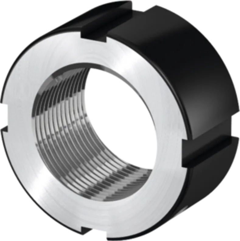
A lock nut does more than stop a bearing from loosening: its thread, seating face, and locking feature determine where the bearing sits and how much preload reaches it. By the end, you will be able to distinguish lock-nut designs, specify the accuracy features that matter, install one without damaging the bearing, and verify the result with measurements rather than tightening feel.
Key takeaways
- Match the lock nut design to speed, load, access, and adjustment needs.
- Check thread accuracy, face runout, nut roundness, and locating shoulder quality.
- Use the specified tightening sequence to avoid false preload and bearing damage.
- Measure axial position, runout, and preload after tightening—not just torque.
How a precision lock nut controls bearing position and preload
A bearing can shift even when its nut has not visibly loosened. A precision lock nut clamps the bearing ring against a shaft shoulder or accurately ground spacer, creating a controlled axial force that prevents axial movement and bearing creep during rotation.
Its fine, accurately formed thread limits how far the nut advances per turn. The seating face must remain square to the shaft axis; a tilted face pushes the ring unevenly, changes the bearing contact geometry, and increases runout. Locking then holds that established position rather than serving as the positioning method.
Set preload from a defined axial displacement, spring-force reading, or direct preload measurement. Torque alone is unreliable because thread and face friction can consume much of the applied torque; validate the chosen method with the actual shaft, bearing, lubricant, nut, and assembly sequence.
After tightening, settling and embedment can reduce the clamping force, causing preload loss. Clean the threads and contact faces, remove burrs, seat the assembly through a controlled tightening or run-in procedure, and verify the final position after stabilization.
The nut also has to preserve alignment across operating temperature and speed. Shaft growth, housing growth, bearing heating, centrifugal effects, and elastic deflection can raise or reduce preload, so a cold stationary setting is not automatically the correct running condition.
Which locking design fits the assembly?
Choose by what must stay fixed: bearing axial position, preload, speed, access, and serviceability. A standard hex nut is cheap, but thread and seating-face variation make repeatable preload difficult. A precision lock nut earns its place when its geometry and locking force belong in the accuracy stack.
| Option | Accuracy and locking behaviour | Best fit and trade-off |
|---|---|---|
| Precision lock nut | Controlled thread, face runout, and positive locking | Bearing location and repeatable preload |
| Standard hex nut | General-purpose clamping; no precision locking feature | Low-cost joints, not precision bearing adjustment |
| Slotted nut with cotter pin | Prevents rotation after alignment; pin clearance limits fine adjustment | Safety retention where preload accuracy is secondary |
| Jam nut | Two nuts resist rotation through opposing thread forces | Simple retention, but adds stack height and preload variation |
| Clamp nut | Clamps the shaft or sleeve through a split or radial mechanism | Fast locking where thread friction alone is unsuitable |
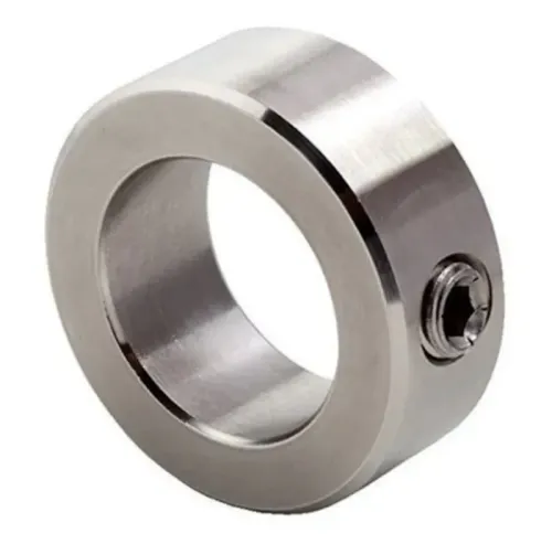
| Shaft collar | Clamps directly around the shaft; does not set bearing preload | Axial stops and light-duty positioning |
| Fine-thread precision nut | Small axial movement per turn enables precise adjustment | Preload tuning; vulnerable to damaged fine threads |
| Radial-locking nut | Locking screws or radial elements secure the nut without rotating it | Compact assemblies; check shaft marking and balance |
| Axial-locking nut | Face locking preserves the set position through axial clamping | High repeatability where a clean shoulder is available |
| Integral locking screw or washer | Built-in feature simplifies retention and service | Choose when access, vibration, and reassembly matter |
For a spindle, favour a precision design whose locking action does not shift the nut during tightening. Verify the shaft shoulder, thread runout, and bearing seat first; no nut compensates for a crooked shoulder or trapped burr. Fine threads improve adjustment, while radial or axial locking determines how securely that adjustment survives operation.
Which specifications determine accuracy rather than just fit?
A nominal thread diameter only tells you whether the nut can start on the shaft; it does not tell you where the bearing will finish. Specify the thread pitch and thread tolerance class, because pitch controls axial travel per turn and excessive clearance harms centring and repeatability.
State the thread direction too: a rotating shaft can loosen a nut with the wrong handedness.
| Specification | What to define | Why it matters |
|---|---|---|
| Thread | Thread form, thread pitch, diameter, tolerance class, and direction | Controls axial travel, fit, alignment, and loosening tendency |
| Seating geometry | Nut-face runout, face squareness, width, and surface finish | Prevents the bearing ring from tilting as the nut tightens |
| Construction | Material and hardness | Resists face distortion, thread wear, and damage during repeated adjustments |
| Locking method | Axial clamp, fine-pitch interference, locking washer, or radial screw | Determines holding force, shaft damage, and removal repeatability |
| Shaft interface | Shoulder squareness, thread runout, bearing-seat diameter, and burr limits | Sets the alignment stack-up the nut cannot correct |
Do not define preload by torque alone. Choose axial displacement, spring force, friction torque, or direct preload measurement, then validate that method with the exact shaft, bearings, nut, lubricant, and assembly process.
For reassembly, remove and reinstall the nut using production tools; accept it only if axial position, bearing friction torque, and spindle runout remain within defined limits. Verify matched angular-contact bearings have the specified orientation and contact the intended ring.
How do you install and set preload without damaging the bearing?
Set the target before turning the nut: use the bearing maker’s specified bearing preload or endplay, accounting for speed, load, shaft and housing expansion, frictional heating, and elastic deflection. Torque alone is not a reliable preload measure because thread friction can vary widely.
1. Inspect the shaft shoulder, bearing seat, thread runout, and nut seating face. Remove burrs and contamination, then measure seating face runout against the shaft axis; a tilted face can cock the inner ring and create radial runout.
2. Fit the bearing squarely onto the shaft, applying force only to the ring with the interference fit. Never hammer through the rolling elements. Seat the inner ring firmly against the shaft shoulder without using the lock nut to force a misaligned bearing into position.
3. Install the nut by hand until its face contacts the bearing ring. Rotate the shaft while applying light axial seating force to distribute grease and settle the bearing; stop if rotation becomes rough or torque rises suddenly.
4. Tighten in small increments with a calibrated wrench, checking axial displacement, rotational torque, or endplay after each increment. Use the specified preload value, not a larger torque chosen to obtain more rigidity.
5. Lock the nut without changing its position, then rotate the assembly by hand and check torque and runout. Run the bearing through its specified break-in cycle, monitor temperature, and stop if friction or heat rises sharply.
Impact tightening can brinell raceways, while excessive bearing preload increases friction, noise, and fatigue risk. Recheck the setting at operating temperature because thermal growth can turn a correct cold adjustment into damaging preload.
How do you prove the assembly is accurate after tightening?
Use a measurement record, not the tightening torque alone, to prove the lock nut delivered the intended position. Torque varies with thread and face friction, so validate it against the exact shaft, bearing, lubricant, nut, and assembly method.
| Measurement | How to check it | Evidence of acceptance |
|---|---|---|
| Axial position and axial play | Seat the shaft against a reference, apply the specified axial force, and read displacement with a dial indicator | Position and axial play remain within the drawing limit |
| Rotational torque | Rotate the shaft through several revolutions with a calibrated torque transducer | Breakaway and running torque match the validated range, with no tight spot |
| Shaft runout | Sweep a dial indicator on the shaft journal and bearing reference surface | Total indicated runout stays below the assembly limit |
| Temperature | Run the assembly at operating speed and record bearing housing temperature and ambient temperature | Temperature stabilises below the bearing and lubricant limits |
| Reassembly repeatability | Remove and reinstall the nut using the production method, then repeat the checks | Axial position, rotational torque, and shaft runout return within defined limits |
Run the checks after repeated seating or the specified run-in cycle. Embedment can reduce preload after the first tightening, while a skewed nut face can create runout even when the shaft is straight.
If OLE Automation Inc supplies nearby linear-motion components, keep their accuracy-grade records with this lock-nut report; a guide or rail cannot correct spindle runout introduced at the bearing seat. A nut that resists rotation has not passed unless these measurements also confirm position and repeatability.
Frequently asked questions
How does a precision lock nut control bearing position and preload?
It clamps the bearing ring against a shaft shoulder or accurately ground spacer, creating controlled axial force that limits axial movement and bearing creep.
Which locking design fits the assembly?
Choose among friction-locking, set-screw, or clamping designs according to shaft thread, rotational speed, adjustment frequency, available access, vibration, and required preload stability.
Which specifications determine accuracy rather than just fit?
Check thread accuracy, nut face runout, nut roundness, perpendicularity between the face and thread, shaft shoulder geometry, and spacer parallelism.
How do you install and verify a precision lock nut?
Clean the threads and bearing faces, seat components correctly, tighten in the specified sequence, then verify axial position, bearing runout, rotation, and preload after tightening.