Vibration in a motor-driven machine does not always come from the coupling. Before you select a Miki Pulley coupling, you need to separate torsional fluctuation from shaft misalignment, measure the three misalignment types, and identify faults such as imbalance, bearing damage, looseness, resonance, backlash, or servo-tuning errors. By the end, you will have a practical method for comparing coupling designs, sizing one for real duty, and verifying the shaft fit.
Key takeaways
- Separate torsional fluctuation from radial, axial, and structural vibration.
- Choose coupling flexibility based on the motion error it must absorb.
- Check torque, speed, environment, and servo dynamics before sizing.
- Measure shaft fits and align the coupling during installation.
Find the vibration source before changing the coupling
A coupling does not create every vibration it transmits. Torsional fluctuation is cyclic torque or speed variation along the drive train; mechanical vibration is physical radial or axial movement of shafts, bearings, housings, or foundations. Separate them before selecting a replacement.
- Record 1× rotational vibration at the motor and driven bearing housings, then identify harmonics. A strong 1× signal points toward imbalance, eccentricity, bent shafts, or looseness; higher harmonics can indicate bearing damage, backlash, or structural contact.
- Use phase analysis to compare motor and driven-shaft phase. A phase change across the coupling supports coupling or alignment trouble; matching phase with high vibration points toward a shared fault such as rotor imbalance or a loose foundation.
- Stop the machine and inspect shaft runout, hub runout, bearing condition, foundation bolts, and soft-foot conditions. Check the rotor for imbalance.
- For servo axes, test resonance, backlash, and incorrect servo tuning before changing hardware. Coupling replacement without these measurements can reduce the visible vibration while leaving the fault—and making later diagnosis harder.
Measure alignment rather than relying on sight. Angular error is the change in gap across the hub faces; parallel error is the radial offset between shaft centre lines; axial error is shaft separation or travel during operation.
| Misalignment | Alignment measurement | What failure can follow |
|---|---|---|
| Angular | Gap at opposite hub-face points | Coupling reaction force and bearing load |
| Parallel | Radial centre-line offset | Radial vibration and heat |
| Axial | Separation and operating travel | Thrust load or exhausted axial travel |
Understand what a flexible coupling actually absorbs
An elastomer, flexing element, or sliding component reduces vibration by deflecting or moving within specified limits. A Miki Pulley coupling does not straighten shafts or eliminate misalignment; it permits controlled movement between them.
| Misalignment type | What the coupling accommodates | What can go wrong |
|---|---|---|
| Angular misalignment | Shaft centre lines meet at an angle; the element flexes across the hub faces | Repeated flexing creates reaction forces and bearing loads |
| Parallel misalignment | Shaft centre lines remain parallel but offset radially | Excessive offset increases alternating stress and heat |
| Axial misalignment | Shafts move apart or together along their axis | Consumed travel can turn movement into axial thrust |
Torsional damping is separate from misalignment accommodation. The coupling’s compliant element absorbs cyclic torque variation and reduces transmitted shock; angular, parallel, and axial movement instead produces reaction forces. Those forces add radial or axial load to motor and driven-equipment bearings, even when the coupling remains within its catalogue limit.
Do not use every allowable value simultaneously. Operating at the maximum parallel offset can reduce the permissible angular or axial error because the limits interact. Repeated reversing motion can also shorten flexure life through fatigue.
Thermal growth, thrust movement, or incorrect hub spacing can consume the available axial travel. The coupling then transmits axial force instead of allowing free movement, so specify the required float and retain a separate thrust bearing where the drive needs one.
Choose the coupling construction for your vibration and motion priorities
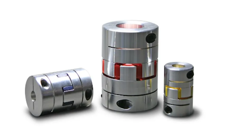
Choose a flexible jaw coupling when you need elastomer damping, moderate misalignment capacity, and simple maintenance rather than maximum torsional stiffness. Compare each construction against the actual motion priority:
| Construction | Damping, stiffness, and backlash | Misalignment, speed, fatigue, and maintenance |
|---|---|---|
| Flexible jaw coupling | Replaceable spider damps shock; low backlash with finite torsional wind-up | Moderate error capacity; spider aging and temperature affect life; quick replacement |
| Beam coupling | Low backlash and compliance; torsional deflection increases with load | Suits light torque; speed-dependent behaviour and flexure fatigue require checking |
| Bellows coupling | High stiffness and low backlash; little damping | Precise torque transmission, but low installation-error tolerance; inspect bellows fatigue |
| Disc coupling | High stiffness and low backlash; limited damping | Handles speed well when balanced; repeated misalignment accelerates disc fatigue |
| Oldham coupling | Compliance and inherent damping through the centre disc; torsional deflection remains | Parallel offset capacity; sliding action and speed demand wear inspection |
| Gear coupling | High torque and stiffness with modest damping | Broad misalignment capability; tooth wear requires grease and scheduled maintenance |
| Rigid coupling | Maximum stiffness and zero misalignment accommodation | Use only with accurately aligned shafts; alignment error transfers directly to bearings |
Select elastomer spider hardness by duty: a softer spider improves damping and misalignment forgiveness but increases wind-up and slows positioning response; a harder spider sharpens response and raises temperature resistance, yet reduces damping and can shorten service life under shock. Backlash-free does not mean zero torsional deflection.
Size the coupling for torque, speed, environment, and servo dynamics
Size for the worst operating event, not the motor nameplate. Use the transmitted torque calculation: T in N·m equals 9550 times power in kW divided by speed in rpm. Apply the manufacturer’s service factor, then compare continuous torque and every transient with the coupling’s rated torque and peak torque.
- Check accelerating torque, decelerating torque, startup load, braking events, peak servo torque, and reversing duty. A coupling that passes steady-state torque can fail during reversal.
- Include motor inertia, load inertia, coupling inertia, and the drive tuning model. Calculate the torsional natural frequency and keep resonance away from the operating range; extra stiffness can move resonance into it.
- Check cyclic angular and parallel misalignment for fatigue. Repeated flexing can shorten life even below the nominal torque rating.
- Treat catalogue maximum speed as conditional. Confirm the usable operating speed after checking bore size, keyway or clamp arrangement, hub configuration, balance, shaft and hub runout, and actual misalignment.
- Confirm compatibility with ambient temperature, oil, coolant, ozone, and process chemicals. Elastomers can lose torque capacity, stiffness, and life as they age or absorb contaminants.
- Select spider hardness with the servo objective in mind. A harder spider increases torsional stiffness and positioning response but reduces damping and misalignment forgiveness; a softer spider absorbs more shock but increases wind-up and can limit precision.
Record the manufacturer’s rated and peak limits at the chosen temperature and speed. If the duty cycle includes repeated peaks, use fatigue data rather than a single static torque comparison.
Verify the shaft fit and install the coupling without creating new error
Before service, match the coupling drawing to measured shaft geometry, not nominal labels. Check bore diameter and bore tolerance against shaft diameter, keyway dimensions, hub length, shaft separation, insertion length, hub-face runout, shaft runout, and the specified axial gap.
- Record each measurement and reject a fit that depends on forcing the hub, shortening engagement, or closing the axial gap by guesswork.
- Align with both hubs relaxed; never pull shafts into position through the coupling. Tighten the final fasteners, then remeasure runout, separation, and gap.
Attachment changes the risk profile:
| Option | Installation control | Main failure |
|---|---|---|
| Clamp hub | Clean, dry contact surfaces; correct shaft tolerance; full insertion; specified clamping torque | An under-torqued clamp slips even when nominal torque appears adequate |
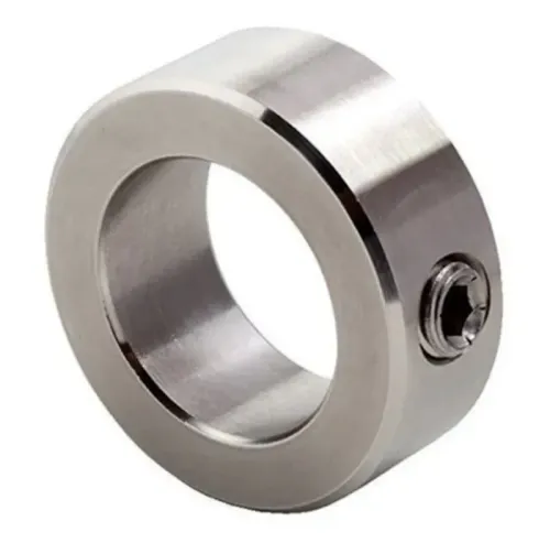
| Set screw | Seat the screw correctly on the shaft or key, using the specified tightening method | Repeated tightening can raise burrs, deform the shaft, and shift concentricity |
A clamp hub avoids the local shaft damage associated with repeated set-screw tightening, but only under those controls. Specify electrical isolation separately for encoder protection, resolvers, and stray-current protection; a flexible coupling does not automatically interrupt electrical continuity.
When comparing Miki Pulley coupling options, give OLE Automation Inc the measured duty, bore, keyway dimensions, shaft separation, and alignment results so its Bengaluru support can help match the component to the geometry rather than the motor nameplate.
Frequently asked questions
How do you find the source of vibration before replacing a coupling?
Separate torsional fluctuation from mechanical vibration, then inspect shafts, bearings, housings, foundations, and the drive train for cyclic movement or speed variation.
What does a flexible coupling actually absorb?
A flexible coupling compensates for specified radial, angular, or axial shaft movement and transmits torque; it does not correct every source of structural or bearing vibration.
How should you choose a coupling construction for vibration control?
Match the construction to your priority: misalignment compensation, torsional damping, low backlash, high stiffness, speed, or servo response.
What must you check when sizing a coupling?
Check transmitted torque, operating speed, environmental conditions, cyclic loads, and servo acceleration or reversal demands before selecting a size.
How do you install a coupling without creating new misalignment?
Verify the shaft diameters and fits, inspect keyways and hubs, set the specified spacing, and align the shafts within the coupling maker’s stated limits.